ESP8266 LEDbar websocket demo
The main purpose of this module will be display water level information on LED bargraph and turn on/off relay depending on data received from server. This will also provide an option for manual override, for emergency switch off sensorio. All communication with server will be made through websocket connection established to the server.
Base design
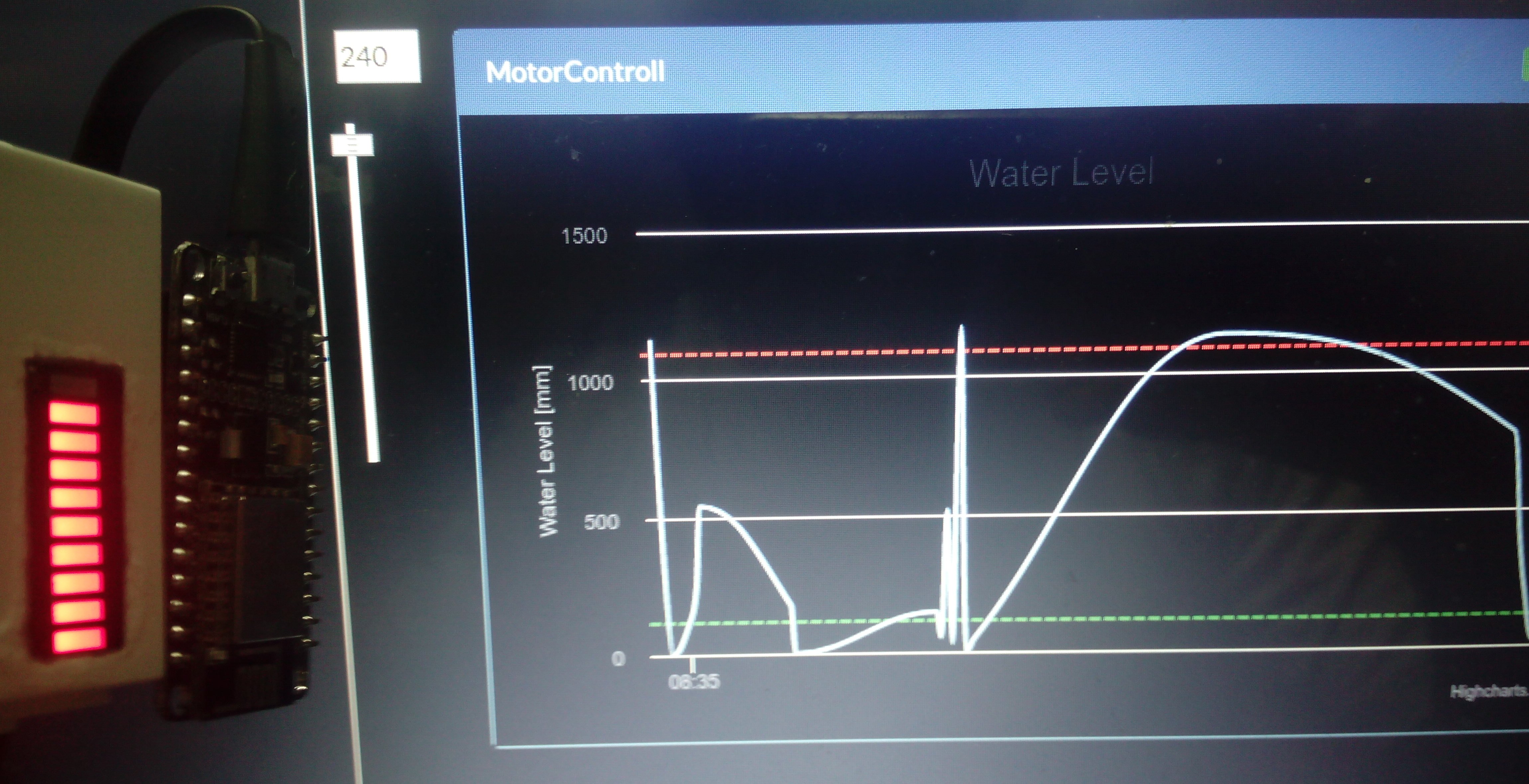
This module will be placed on wall socket to indicate water level and for motor switching. This module make use of NodeMcu ESP8266 microcontroller, which is used to establish websocket connection to the server. Water level information will be received from server which provided by sensor module. Then, water level will be indicated by using LED bargraph.
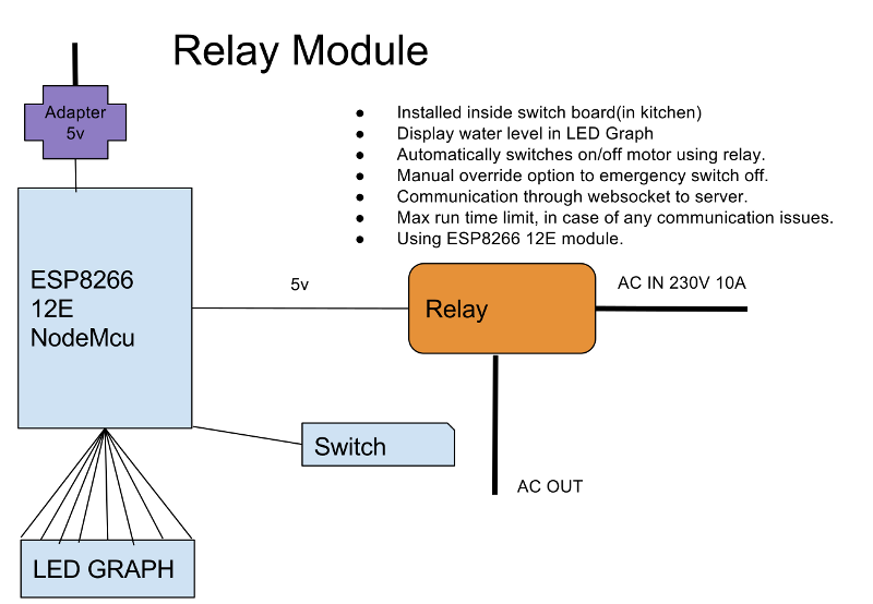
Relay Module Architecture
Go Shopping
In this build i a a have used NodeMcu 1.0 with 12E. if you are using ESP8266 12E directly please make sure that you provide stable 3.3 power supply.
| Item | Item | Qty | Price |
|---|---|---|---|
 |
NodeMcu 1.0 with ESP8266 12E | 1 | US $2.78 |
 |
10 Segment LED Bargraph | 1 | US $0.25 |
 |
Resistors | 10 | US $0.01 |
 |
Relay Module | 1 | US $1.20 |
 |
Jumper wires | 15 | US $0.03 |
Total cost of components is around US $5 (₨ 325). Please have soldering iron, solder,And a plastic box which will be needed during the build.
Start Wiring
Wiring of this relay module is fairly straightforward. For this build i will be using NodeMcu which i have in hand. if you are using ESP8266 directly make sure that your ESP module have necessary GPIO pins available.
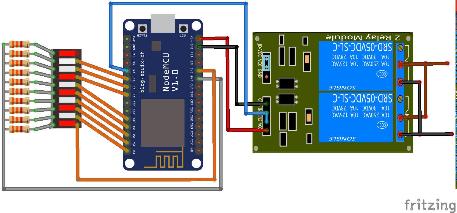
Relay Module Diagram
We are using 10 3.3kOhm resistors to limit current flow to the LEDs. This will reduce the current flow and reduce power usage. Since these LEDs are active most of the time, it is good to limit brightness(hence power usage) to the LEDs. 3.3kOhm resistors is a good choice to give it required brightness. Please feel to select resistor value to balance between brightness and power usage.
In diagram i am using 2 channel relay board. This is because these relays are used to control power for 1.5HP 230v AC electric motor. This motor will use a maximum current of 10A. This is not an average current usage, it is FLA(Full Load Amperes).You can find chart . Each SRD-03VDC-SL-C SONGLE relay can handle maximum of 10A, to have some safety i have used 2 relays in parallel to split current. In relay board i soldered 2 relays together so that it will active same time. In this build i have used 3V relay. If you are using 5V relay(which is commonly available) please connect VCC and GND to appropriate power pins on nodeMcu. Relay module using NodeMcu, 10LEDs and 2 Relays, please do make sure that power supply can provide at least 500mA current.
Software
The base software parts we are using is same as Sensor Module. The websocket connection established to server via websocket. Once websocket connection is established registration request will be send, which include module ID. Server receives registration request and update module as online, which will be broadcasted to other connected modules (like Admin module). Server will also send response message which include all the initial data required by the module.
The registration acknowledgement send by the server include configuration values. This includes maximum and minimum water level, trigger and cutoff percentages and maximum run time. These values is necessary for relay module for taking decisions based on water level. Once server receives water level information from sensor module on water tank, it will forward this data to all the listening modules, including relay module. Relay module use this information to calculate water level percentage.
In every water level update relay module checks if it is below trigger percentage, if yet it will turn on turn on motor by setting relay GPIO to high. Same time it will send an update to server to inform motor has been activated. Once water level reached cut-off level it set relay GPIO to low, turning off the motor and updating the server about the same.
Failover
The module should consider multiple failover conditions to prevent motor from running indefinitely. These possible cases is include but not limited to,
- Connection problem with internet.
- Wifi connection problem.
- Server failure (Websocket instance stopped responding)
- Sensor module stopped working (No update on water level)
These problem can be addressed by using,
1.Manual override switch
This is simple and straightforward solution. We will provide a switch to the user to turn off entire relay module. Which will intern turn off the relays and water pump motors.
2.Maximum motor running time
In this approach we will provide Relay Module with max_run_time value. This value indicate maximum time motor need to run to full water tank in seconds. For example assume it need 120 seconds to fill water on tank. Once motor turn on by motor in every second, it will start reducing that count in every second. When remainig_time reaches 0. It will automatically turn motor off the motor.
Final Build
Future enhancement
- Another push button on override system other than existing one.
- Move entire water level calculation logic to the server.