This will be my first experiment on working with ESP8266 wifi module. Purpose of this module is to send water level information to server via WebSocket. Since this module will be place on terrace, it should have independent power supply like solar panel.
Main Objective
- Measure water level/distance and send it to server.
- Able to work 24/7 without any external power supply
- Power full module by solar panel and LiPo 18650 Battery.
- Create stable 3.3v power supply for ESP8266 and ultrasonic module.
- ESP8266 connect to wifi network & and establish WebSocket connection.
- Measure distance using ultrasonic module in mm.
- Reject any noise in measurement and calculate average distance value.
- Send distance information to the server.
Base design
Sensor module will use ESP8266 as microprocessor and as Wifi module, which only cost around $3. The distance measurement will be done by ultrasonic distance sensor module. Ultrasonic module which we are using is vulnerable to noise, and sometime provide inaccurate reading, so we need to ensure software we wrote is accommodating for that and assure any nice measurement by the sensor will get rejected. ESP8266 will connect to WiFi Network and establish a WebSocket connection to the server, once connection is established, distance measurement is taken and send to the server.
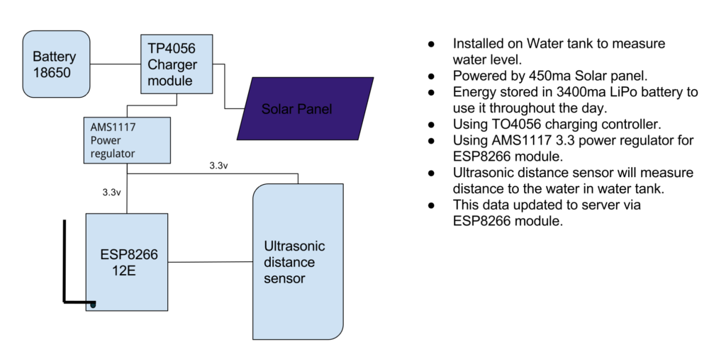
Sensor Module Architecture
Sensor module will be placed in a water tank where power supply is hard to reach. So it need an independent power supply which solar panel is the only option. In an average day usable sunlight only available for 6-8 hours, to make it work 24 hours, we need battery to store energy. We will be using 18650 3400mA LiPo for this purpose. Another challenge is ESP8266 only work in a very limited voltage range, around 3v-3.6v. To make voltage stable around this range, we will use 3.3v voltage regulator.
Go Shopping…
Following is the list of components needed for a stable long term build.
| Item | Item | Qty | Price |
|---|---|---|---|
 |
Solar Panel 5v 500mA | 1 | US $6.90 |
 |
Ultrasonic Module HC-SR04+ 3.3v | 1 | US $0.86 |
 |
FTDI With 3.3v supply | 1 | US $2.22 |
 |
ESP-12E ESP8266 ESP 12E Wifi Module | 1 | US $3.25 |
 |
TP4056 LiPo Charging Board (Protected) | 1 | US $0.44 |
 |
Jumber wires (Mix) | 10 | US $0.03 |
 |
1K Ohm Resistor | 2 | US $0.01 |
 |
HT7333( or LD1117V33) 3.3v Voltage Regulator | 1 | US $ 0.14 |
 |
Panasonic 18650 LiPo 3400mA Battery | 1 | US $5.70 |
Please note ultrasonic module we required is HC-SR04+ which work on 3.3v, Normal HC-SR04 modules only work on 5v
Please have soldering iron, solder,And a plastic box which will be needed during the build. For voltage regulator choose HT7333 in preference to LD1117V33, since it have low drop off voltage. The power supply section is represents 70% of the cost, please feel free to choose low cost low capacity 18650 battery & solar panel for experimental purposes(like ultrafire 18650 500mA).
Total cost of components will be around US $20 (₨ 1300). You can find components in my AliExpress List.
Start Wiring
Since we have all the components we can start wiring it up properly. This sections will show the wiring when the module is in use. For uploading software to ESP8266 we need to have another setup which connect to an FTDI(USB serial adapter) and upload our compiled program into ESP8266 memory.

Sensor Module Connections
Please note TP4056 and 18650 battery is not exact representations.
We can start with Solar panel, some panel comes with attached USB cable, for some module we need to solder wires to +ve and -ve terminals. Solar panel inputs goes to the TP4056 inputs which is near micro usb port. Next battery is connected to bat+ and bat- terminals on TP4056. TP4056 can handle upto 1A so it is safe to attach solar panel up to that current. Next we need to connect TP4056 out +ve and -ve terminals to HT7333 or LD1117V33 voltage regulator.
Prefer HT7333 over LD1117V33 because it have less quiescent current and drop off voltage. HT7333 Quiescent Current is 4µ Where LD1117V33 have 7mA
.
Here will do some calculations to find-out the requirement of solar panel power and LiPo battery. ESP8266 consume around 110mA(Since data transfer is very less). Ultrasonic module around 15mA and LD1117V33 Quiescent Current is 7mA. In a day module need an average of 3200mA. So an expected average sunlight of 7 hours we need solar panel which generate approximately 450mA(3200/7) of current. Also, LiPo battery should able to store a minimum 2300mA of energy. This completed the power supply section of the module.
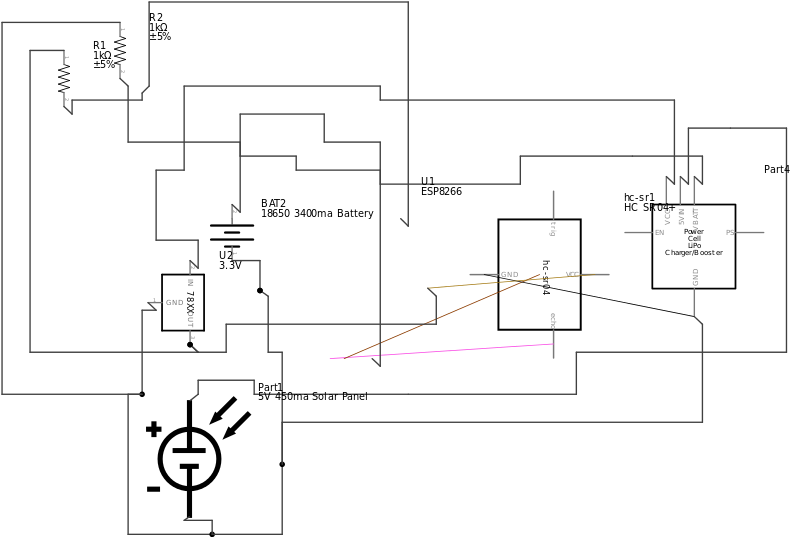
Sensor Module Connections Diagram
Now we have a stable 3.3v 24hours power supply. Connect GND and Vout of voltage regulator to GND and VCC of ESP8266 and Ultrasonic module. Next we need to connect CH_PD to VCC and GPIO15 to GND though a current limiting resistor which help ESP8266 boot to required booting mode. Resistors is not mandatory but will be helpful to avoid any unwanted current flow to ESP8266 GPIOs. Only data connections we need to place is from ultrasonic to ESP8266. HC-SR04+ Trigger and echo pins, Trigger used for sending an ultrasonic pulse and Echo pin is for echo received. Both should connected to any of the GPIOs of ESP8266, in this case GPIO14 and GPIO12.
Soldering ESP8266 can be tricky since it has very less spacing between pins. I have used both normal single core cables and LED pins as a connection, Pre soldered ESP8266 PCBs are also available. Choose an option that is comfortable to you.
.
Software
Please refer online for how to connect an ESP8266 12E module to an FTDI, only thing we need to care is to use 3.3 supply to ESP8266, do not use 5v supply.
We will be using Ardrino IDE for the programming ESP module. We need to install following package to Ardino IDE.
- ESP8266
- ESP8266 Wifi
- ArduinoJson By Benoit Blanchon
- WebSockets By Markus Sattler
In IDE select Board as “Generic ESP8266 module” and Flash size as 4M. Set appropriate Upload speed and make sure that it is the same given in the code. Code is most of the part self explanatory. The communications to server please refer another blog post(Will add in a future blog post) describing the same. The main functionalities are.
- Initialize module with by setting TRIGGER GPIO as output and ECHO as INPUT
- Provide Wifi credentials TO WifiMulti object and init connection
- Once wifi connection is established, Init WebSocket connection
- Once WebSocket Connection event is fired, Send registration request to server with module key
- Server will register module as online, and send response back to module
- Module received the response back from server and start measurement
- Measurement will be taken in 5 seconds intervals.
- Multiple measurement is been made and use logic filter any noice(inaccurate) values.
- Calculate average water level information and send it to the server.
HC-SR04 noise rejection Logic
HC-SR04 work on the basic of ultrasonic sound, it will send an ultrasonic pulse which reflected by object and reflected back to HC-SR04. The time between them is measured and using the speed of sound we can calculate distance to the object. Which will work fine on optimal environment with an accuracy of 1-5%. But on some environment, like in this case some background noise will cause highly inaccurate outputs. This will happen only for 3-4 measurements in a sample of 100 measurements. But it will affect the average value. So its good to have a logic using that we can reject any unexpected noise distance measurement.
[cpp]
/**
* measure distance with noice rejection.
*/
int mesureDistance()
{
int i, total_count = 0, total_distance =0,distance, values[10], average, temp, new_count = 0;
for(i=0; i<5; i++){ distance = mesureSingleDistance(); if(distance > ULTRASONIC_MIN_DISTANCE && distance < ULTRASONIC_MAX_DISTANCE) { total_distance += distance; values[total_count++]=distance; Serial.printf("Value %d...\n", distance); } } if(total_count > 0) {
average = total_distance / total_count;
total_distance = 0;
Serial.printf(“Average %d…\n”, average);
for(i=0; i
total_distance += values[i];
new_count++;
}
}
if(new_count > 0) {
return total_distance / new_count;
}
}
return 0;
}
[/cpp]
The logic is fairly straightforward, First Line 8-15, 5 measurements is taken and only the value which is within the expected min and maximum range is moved into an array. From line 19-30 original filtering happens. First calculate the average values of the measurement and any value which is more than 10% difference from the avg value will be removed from array. The average value of the array is again calculated and will considered as final measured value. The whole process only took 10ms.
The whole communication to server happens in JSON encoded format. ArduinoJson library is very helpful for encoding and decoding JSON.
Final Module
Future upgrades
- Reduce energy usage by usage of sleep modes on ESP8266
- Smart management of measurement delay (When motor is on, high measurement rate)
- Use original Panasonic 18650 Battery
- ESP8266 OTA software flashing
Hope this post helpful in for you in making you more inspirations for the possibilities of IOT. As a webDeveloper by profession i am new to IoT and electronics, please leave your thoughts,suggestions or any mistakes you found on comments. If you find this useful please feel free share it. Thanks.