Temperature humidity sensor & IR Motion sensor
Raspberry Pi connected to IR motion sensor and DHT11 Temperature humidity sensor. IR motion sensor will provide a high output when it detect a motion in front of it. This will be used to detect motion in front of mirror. DHT1 sensor will provide accurate temperature humidity reading of the room. This data will be constantly feeded to the server.
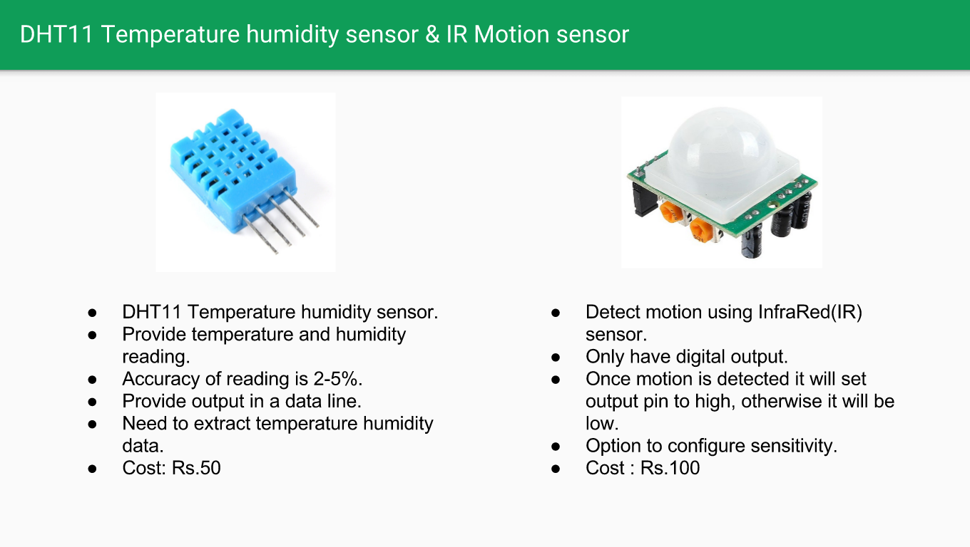
DHT11 Temperature humidity sensor and IR motion sensor
Controlling these sensors and LED Strip is done by a background PHP script. this script as similar module connect to server through websocket to send data.
LED Strip color control
LED strip is used as backlit for magic mirror. For changing color we have to use LED strip with separate diodes for Read, Blue and Green. Here i have used 5050 LED strip which have separate connections for Read Blue and Green. By varying current through each of these channels, we can control brightness of each color, thereby creating any color.
This produces while implementing color change with Raspberry Pi. First one is the main voltage difference between Raspberry Pi GPIO pins and LED Strip. Raspberry Pi GPIO have 3.3voltage while LED strip requires 12V. This is archived by using TIP120 Darlington transistor. Which actually allows to control the flow of current from emitter and collector by varying base voltage. So base will be connected to GPIO pin and emitter will connected to led strip. Same setup is required for 3 color channels.
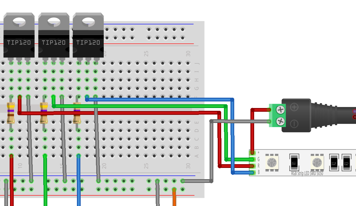
5050 RGB LED Strip interfacing to raspberry PI
Once background PHP process received command from server to change color though websocket, it first decode the color value. The server send color value as hex code (Eg:FF1532). This will get decoded into respective RGB values each ranging from 0 to 255. The lower the range of color we use, lower will be processor conception by software GPIO. Once color code is decoded which will then send to respective pins to start PWM.